CB-B gear pump structure and installation method
CB-B gear pump structure and installation method
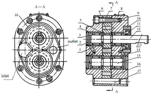
CB-B gear pump structure drawing:

1-Bearing outer ring ,2- Plug head ,3- roller ,4- Rear pump cover ,5- key, 6- gear, 7- pump body ,8- front pump cover, 9- screw ,10- pressure ring ,11- seal ring ,12- Drive shaft ,13- key ,14- purging hole ,15- driven shaft ,16- purging groove ,17- locating pin
CB-B gear pump structure description:
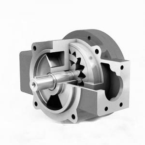
1, gear pump is mainly composed of pump body, gear, front cover, back cover, bearing, skeleton oil seal and other parts.
2, pump body, front and back cover to choose HT250 gray cast iron, the gear is made of high quality powder metallurgy, pump shaft selection of 40 cr steel hardening processing, bearing oil free choose SF - 1 bearing or needle roller bearing, seal the eyes lips butyl rubber (note: the oil temperature at 60 ℃ to 200 ℃ or corrosive medium, ordering), make the pump work stable performance wear resistance, long service life, the use of helical gears, the sound will be lower.
CB-B gear pump installation points:
1. If the pump shaft is connected with the motor, elastic coupling shall be used, the concentricity shall be within 0.1mm, and the hand-rotating coupling shall not be too tight or of uneven weight.
2. Pump shaft and hole connection, pump shaft with hole clearance should be in 0.02-0.03mm between not to force knock, so as not to make the pump shaft stuck.
3. The inlet pipe diameter of the pump shall not be less than or greater than the inlet diameter of the pump, the inlet pipe design shall be as short as possible, with as few bends as possible, and the outlet pipe diameter shall not be less than 3/4 of the inlet pipe diameter.The inner wall shall be cleaned with high pressure oil before the installation of the pipeline, and there shall be no hard particles and sundry. The inlet pipe shall be equipped with a filter, the flow rate of which shall be twice that of the pump. All joints of the inlet pipe shall be sealed reliably without air leakage.

